DESIGN AND CONSTRUCTION OF A SUCTION TABLERoy L. Perkinson
ABSTRACT—A design for an inexpensive, easily disassembled and cleaned suction table of simple construction is presented, with a description of the materials used. The application of the table in paper conservation treatments is briefly described, and its use for textile conservation is suggested. SINCE ITS INTRODUCTION by Marilyn Weidner in 19741 the suction table has generated considerable interest among paper conservators. It has become an important tool in solving a variety of problems previously thought difficult or impossible to treat. The table described here was contructed by the paper conservation laboratory at the Museum of Fine Arts in 1976 and has been in regular use since then. The design is only one of many possible variations, but it is hoped that the specific details of construction will be of interest to others who are considering building their own versions. Three general guidelines were observed in the constuction of the table: it should not be extremely expensive; construction should be simple and should not require unusual or highly specialized tools; it should be possible to replace or clean the components easily. In this instance construction was simplified by the discovery of a used drafting table which was still in sound structural condition. It was the right size; its metal legs and supports, obviously of an early vintage, were old enough to be potentially attractive rather than merely functional; and its wheels insured that it would be possible to move the table without difficulty. An added bonus was the fact that both the height and angle of the table top were adjustable. The ability to place the table in a vertical format once the art is positioned is an important feature (Fig. 1). Accidental dripping of liquid onto a picture's surface while spraying is a real possibility with unpleasant results. Not only is this danger limited by upright positioning, but solvents can be applied more evenly using a vertical mode.
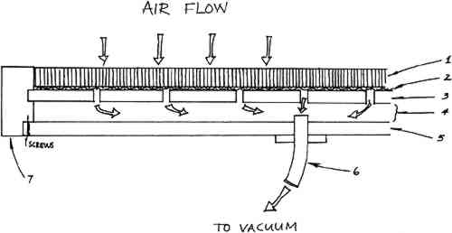
The original top of the table was removed and replaced with the suction table itself, shown in Figure 2 and diagrammed in Figure 3. A shallow plenum space was incorporated in the bottom of the table to promote efficient and uniform airflow over the entire surface. The holes in the upper layer of plywood are �″ in diameter and are spaced at 4″ intervals. This distribution was arrived at more by intuition than calculation, and seems to have been quite successful. A layer of �″ hardware cloth2 was selected as a simple, inexpensive means of facilitating air flow between the honeycomb3 and the plywood. Without this layer, air would be unable to pass through the honeycomb except in those areas directly above the holes in the plywood. The particular honeycomb panel I selected is one inch thick, and the cells are a nominal ⅛″ diameter, with wall of 0.002″ aluminum, but other sizes and thicknesses are available.
The wooden parts were put together with waterproof resorcinol glue and screws, and joints between the two plywood layers and the outside frame were rabbetted to make them more secure and airtight. After assembly, all wooden A birch veneer plywood cover was constructed to slip over the top of the table when not in use, providing both protection and an extra work surface. Finally, the metal supports and legs were painted bright red, a vast improvement over the previous battleship gray. The overall size of our suction table is approximately 44″ � 60″. It is certainly not necessary to construct a table of this size. Dimensions of about 30″ � 40″ or even slightly smaller would probably be useful for many projects, yet I have found the large size of our table helpful on several occasions. When the table is in use it is attached to a heavy duty wet/dry vacuum To facilitate operation of the table an electrical switch was mounted on each of One of the practical problems associated with the use of the table is that the vacuum cleaner is rather noisy. Although this is not too troublesome for short periods of operation, it may be objectionable if the table is in continuous use for a long time. In addition, if flammable solvents are used on the table, there is the theoretical possibility of ignition. The path of air through the vacuum cleaner is essentially independent of the air passing around the motor, but the design of the motor housing is such that air leaving the holding tank cannot be prevented from coming in contact with the motor. Therefore we explored two alternatives: using a different type of motor in a remote location, or constructing a different housing for the motor. Since the planned renovation of our laboratory will permit the installation of an explosion-proof motor totally outside the work space, we are proceeding with the first alternative, and the table will then be attached to an exhaust tube within the laboratory. The second alternative could be accomplished, I believe, by purchasing a motor of the correct size and type, then constructing a soundproof container for it and attaching an exhaust tube to it which would conduct vapors to a safe distance away, or possibly directly into an existing fume exhaust system. The Lamb Electric two-stage by-pass vacuum motor might be satisfactory for this purpose.6 (I am grateful to Tim Vitale, Intermuseum Laboratory, for this suggestion.) I would like to make a general observation on the use of the table which may be so obvious that it could be overlooked. The work room in which the table is used should be very clean so that the air drawn into the table will be as free as possible of particulate matter. Air is, after all, being drawn through the picture and paper can act as a filter for air-borne particulate matter. To check the air quality, it would be advisable to run the table for an hour or two using a sheet of blotting paper in place of a picture and leaving only a very small area uncovered by the masking material. If Since the construction of our suction table, we have found it useful for a variety of problems such as reduction of stains from water or pressure sensitive tapes, conditioning/drying of moist paper to room humidity, and drying pictures that were executed in a medium that might easily offset during ordinary drying between blotters. We have also observed that the table may be helpful in other areas of conservation. Our textile conservator, Leslie Smith, has found it useful for certain procedures such as the removal of deposits of glue from textiles whose colors would otherwise be adversely affected by overall treatment with water. REFERENCESAIC Bulletin, vol. 14, no. 2, pp. 115–122. Hardware cloth is a heavy, open-weave wire screen and is available at many hardware stores or lumber supply houses. Honeycomb panels are available from Hexcel Corporation, P.O. Box 709, Bel Aire, Maryland 21014. Pullman model JB-102 industrial vacuum cleaner. Pullman/Holt Products, Division of Purex Corp., 123 Medford Street, Malden, Mass. 02148. Clarke model 612 vacuum cleaner. Clarke-Gravely Corp., 2800 Estes Street, Muskegon, Mich. 49441. For the address of the nearest distributor of flexible rubber sheeting write Hygenic Rubber Products, 1245 Home Avenue, Akron, Ohio 44310. Lamb Electric two-stage by-pass universal vacuum motor with tangential discharge, model no. 115334, available from W.W. Grainger, Inc., stock no. 2M174. Branches of W.W. Grainger are located in many cities.
 Section Index Section Index |