MONITORING THE FADING AND STAINING OF COLOR PHOTOGRAPHIC PRINTSHenry Wilhelm
ABSTRACT—Methods are described for the long-term monitoring of visual changes which can occur in color photographs kept in the dark or exposed to light on display. A photographic color densitometer is used to measure changes in stain levels and in the integral red, green, and blue optical densities of the images, which consist of cyan, magenta, and yellow dyes or pigments. Procedures are given for making polyester print overlay sheets to record precise measurement locations. A separate “fading monitor,” which can be used to distinguish between deterioration caused by exposure to light and that which occurs in dark storage, is described. A system of long-term densitometer calibration using refrigerated photographic gray scales and color scales is outlined. The types of visual and physical changes which can occur with common types of color photographs are described. Quantitative limits for color print image deterioration which take into account stain formation, color balance changes, and losses in high-and low-density portions of the image are suggested. 1 INTRODUCTIONPEOPLE OFTEN WANT TO display original color photographic prints in a museum, gallery, or archive; unfortunately, however, such display exposes the prints to light which will cause gradual image deterioration in the form of fading and changes in overall color balance. In addition, many types of color prints are subject to stain formation. Such stains are most readily visible in the lighter areas of a print and are usually yellow; with a number of common color print materials, stain formation over a period of time may be the most obvious type of image deterioration. Compared with most other types of artistic media, color photographs generally fade and/or stain fairly rapidly when displayed, and many types of color prints are quite unstable even when kept in the dark. Changes which take place in dark storage can usually be arrested only by placing the photographs in low-temperature and low-humidity storage. At normal room temperatures, dark storage changes (often referred to as dark-fading)1 will continue whether or not a print is on display. Thus, when a print is displayed, the total change that takes place is some combination of dark-fading staining and light-fading/staining. Light-fading is caused by both visible light and ultraviolet radiation. For most types of color prints displayed in normal museum display conditions, image deterioration caused by ultraviolet radiation is much less significant than changes caused by visible light and storage at room temperature. Museum display conditions for color photographs vary widely from one museum to another and even within a given institution. Typically, color prints are illuminated with tungsten lamps of about 2,800–3,200�K; intensity on the print surface is about 130–325 lux (12–30 footcandles) for about 10 hours per day. The light is normally filtered by the glass sheet used in framing the prints. Low illumination levels of about 50 lux (5 footcandles) have been suggested for display of color photographs; however, the author believes that this level is too low for proper viewing of most color photographs. Shorter display times at higher illumination intensities are preferable. With many common types of color photographs, such as Kodak Ektacolor 74 RC chromogenic2 prints (often incorrectly referred to as “Type C” prints), dark-storage reactions may predominate when the prints are displayed under low-level tungsten light; the use of extremely low-level tungsten illumination on the order of 50 lux (5 footcandles) may result in little if any gain in print life. High-intensity accelerated light-fading tests often produce data which do not give an accurate indication of actual long-term fading and staining characteristics,3 and long-term To determine the changes that take place in a color print over a period of months or years, it is necessary to measure periodically the color and optical density of a print directly. Alternatively, the changes can be measured indirectly with a “fading monitor” made of the same type of color print material as the photograph in question and subjected to the same light, temperature, and relative humidity conditions as the color photograph. Measurements are made with an accurate electronic color densitometer designed for photographic use. The quantitative data thus obtained indicate at which point in time slight—but visually significant—changes have taken place so that the user knows when to retire the original print to cold storage in the dark, substituting copy prints for study and display purposes. Table I shows the quantitative limits of acceptable change suggested by the author. TABLE I Because the relationship between dark-fading/staining and light-fading/staining of the dye sets used in the many types of color photographic materials is complex, and for a variety of other reasons, measurement of the total light exposure received by a print using the British Wool Standards, NBS Fading Papers, integrating photometers, and so forth will generally not indicate accurately the degree of deterioration of a color photograph during long-term display and/or dark storage. The color print montoring procedures described below can also be used to measure changes in monochrome photographs such as silver-gelatin and silver-albumen prints.5 Likewise, yellowing and other forms of deterioration in works of art on paper and in other paper objects can be monitored during long-term display and storage. The measurement techniques described here are also applicable in documenting changes in objects after conservation treatments. Changes in watercolors and paintings can be measured using similar procedures, but because of the wide variety of colorants used in paints, a spectrophotometer may have to be employed6 in addition to, or in place of, a color photographic densitometer to ensure accuracy. Color photographic images are composed of cyan, magenta, and yellow colors which have spectral absorption peaks within a fairly narrow range; photographic densitometers are designed to measure colors with these spectral characteristics. While the concept of predetermined limits of change is directly applicable to paper objects, watercolors, paintings, and so forth, the limits selected will probably differ from those suggested here for color photographs. Still, it is important to measure and record the visual characteristics of all objects of these types quantitatively so that any changes in future years can be determined with reasonable accuracy. Basic to any monitoring system is an instrument calibration procedure which assures the continued accuracy and comparability of measurements even after old equipment has been replaced by new instruments of different design. Maintaining system accuracy for hundreds or thousands of years in the future will require careful planning as well as the very long-term preservation of color photographic calibration standards in an unchanged state through the use of humidity-controlled cold storage. Preserved color photographic calibration standards are thought likely to provide more accurate densitometer calibration than would be possible using porcelain plaques or stable pigment standards, which have spectral characteristics different from those of the cyan, magenta, and yellow dyes used in color photographs. 2 DIRECT MONITORING OF COLOR PRINTSOF THE TWO METHODS described in this article for monitoring the fading and staining of color prints, most institutions will choose to measure image changes directly on the prints. Separate “fading monitors” are useful chiefly for research in cases where the fading Suitable color reflection densitometers for print monitoring are available from a number of companies.7Kodak Wratten filter numbers 92 (red), 93 (green), 94 (blue), and Visual 106 are recommended for this application in preference to Kodak Certified Status A filter sets because the Kodak Status A filters are more likely to become obsolete in future years than are the traditional Wratten filters; the Status A filters were designed primarily for Kodak chromogenic materials and may not be well matched to the dye sets used in other types of color photographs. However, some high-quality photographic densitometers are now being supplied only with the Status A filters, and these filters should be used if the Wratten filters cannot be readily installed. Densitometer filters should be replaced by the instrument's manufacturer every 3 or 4 years.8 To ensure maximum life of the instrument, the densitometer should not be used for other museum applications such as photographic process control. In general, readings are taken with the red-green-blue filters; use of the Visual 106 filter is not necessary during the monitoring of most types of color prints, although it should be used in addition to the color filters for the monitoring of monochrome prints. Density data should always be recorded in the standard red-green-blue sequence to avoid confusion. It is not possible to measure image density accurately when a print is framed with glass, so the print should be removed from the frame when density readings are to be made. To avoid direct contact of the densitometer head with the surface of the print, and to provide an exact record of the densitometer reading locations on the print, a thin matte-surface polyester overlay sheet9 must be prepared for each print (cellulose acetate or polyvinyl chloride sheets are not satisfactory because curling and dimensional stability are potential problems), with the print image locations marked on the sheet so that the densitometer head may be registered accurately on the image during each series of readings (Fig. 1). The matte surface of the polyester sheet accepts ink and pencil lines readily; ordinary clear polyester should not be used, as ink will not firmly adhere to the surface and may smear or wear off. The author has found that polyester sheets with one matte side and one glossy side are more satisfactory for this application than sheets both sides of which are matte. The sheet should be cut about 5 cm (2 inches) larger than the print in both dimensions; space on the edges can be used to write identification data, date of preparation, and other information. The polyester sheet material should be 3 mil or 4 mil (.003 or .004 inch) in thickness for general applications; thinner material may be used for prints 20 � 25 cm (8 � 10 inches) and smaller.
Densitometer head locations must be precisely marked on the overlay sheet using a technical pen with a medium point and a suitable stable black ink.10 The glossy side of the polyester sheet is placed down, against the surface of the photograph. The matte side of the sheet is on top, and all ink markings and notations should be on the matte side of the sheet. Great care should be taken to keep ink away from the photograph. It is usually satisfactory to mark the densitometer head locations by tracing the outer edges of the densitometer base plate (Fig. 2). After the densitometer head locations have been determined and marked, the polyester sheet should be removed and a hole about 1.5 cm (� inch)
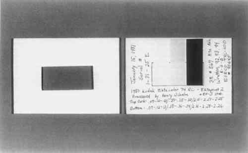
Work areas should be clean, and to avoid putting fingerprints on the photographs, cotton gloves should be worn by the operator. A sheet of bright white matte board or opaque white glass should be placed on the work table and prints placed on this white surface while densitometer readings are made. As most print support materials transmit a significant amount of light, the reflectance of the surface beneath a print may have a significant effect on densitometer readings made in low-density areas of a photograph. For example, readings taken on a dark work surface will usually indicate somewhat higher densities than readings taken on a white work surface; such discrepancies may be quite large with albumen prints and other types of photographs made on thin paper supports. Density readings through the red, green, and blue densitometer filters should be taken at minimum-density locations, low-density locations of about 0.35, and maximumdensity locations. Normally, readings in each density range should be taken in at least three locations (for a total of at least nine reading locations), and the readings should include near-neutral colors if possible. Some of the readings should be taken near the top of the print, where the intensity of illumination during display is usually somewhat higher than it is in the lower areas. Fairly large areas of uniform tones should be selected if possible for reading locations. However, in many photographic images such areas may not be available, so a large number of readings will be required for accurate representation. After readings have been taken, the polyester overlay sheets should be stored flat in a protective polyester sleeve12 or in a high-quality paper envelope. When prints are displayed and are subject to light fading, it is particularly important that minimum-density and low-density (approximately 0.35) areas be carefully monitored, as dye losses in the low-density areas will be much greater proportionally than dye losses in high-density areas (Table II). This relationship between dye loss and density is typical of many types of color print materials; however, some types of prints, such as Polaroid SX-70 prints, may develop stains which alter minimum density behavior. In dark-fading, dye losses tend to be proportional throughout the density range of the color image. Prints which have faded in dark storage do not suffer from the type of highlight detail loss that is characteristic of prints which have faded because of exposure to light. TABLE II 3 COLOR PRINT FADING MONITORUSE OF A COLOR PRINT fading monitor allows one to measure indirectly the changes which take place in a color photograph. All of the colors and tones of a color photograph are obtained by varying the concentrations of cyan, magenta, and yellow image dyes or pigments in the emulsion layers which are coated in three or more layers on the surface of the support material. A few types of color prints, such as Fresson Quadrichromie pigment prints, make use of black as a fourth color; the black pigment is normally present only in high-density (dark) areas of the image. The same three (or four) colors are used to form all the colors in a color print, and a neutral gray patch consists of nearly equal concentrations of the three (or four) image dyes or pigments. The minimum-density patch contains little or no dye or pigment. It is possible to measure changes in neutral gray patches of minimum density, low density, and maximum density and thereby to obtain a reasonably accurate indication of changes occurring in any area of a color print if the three patches are made of the same print material and are processed in the same way as the original print. A single fading monitor should be used with only one color print, and the monitor should be permanently assigned to that print with a serial number. Potential disadvantages of fading monitors include possible differences in print and monitor fading/staining rates which may be caused by differences in materials, processing, or use conditions. Furthermore, as noted above, monitors can be prepared only from print materials and processes which are available in the marketplace: monitors therefore cannot be prepared for most, if not all, older color print materials in a collection. Most institutions will find it more practical and accurate to monitor most of their color prints directly and to reserve the use of fading monitors for special situations; for example, in some cases it may be undesirable to remove a print from its frame repeatedly for direct measurements. 4 PREPARATION OF A FADING MONITORTHREE PATCHES, EACH about 1.3 cm � 3.3 cm (� � 1� inches), should be prepared using print material, processing chemicals, and processing procedures identical to those used with the original print. Any variation from the processing chemicals or procedures used with the original print may affect the fading characteristics of the monitor and may reduce its accuracy. One patch should be minimum density (white); one patch should be a neutral gray of about 0.35 density; one patch should be maximum density (black). Ideally the patches should be printed on the border area of each original print when it is made. However, it is unlikely that this will become common practice, and the patches will usually have to be optically printed in the proper size on a single sheet of print material. As an alternative, entire sheets of material can be printed to the desired density and the sheets cut into the proper size after processing. The three patches should be mounted on the same type of board used to mount the photograph being monitored and should be attached with the same type of adhesive or mounting system (Fig. 3). When it is used, the monitor should be covered with a matte made of the same type of board as that used to overmatte and support the original print. The overmatte should have an opening in the center, and only one-half of each patch should be exposed to light, so that the light-fading and dark-fading functions of the monitor are separated (the overmatte must be essentially opaque to light if the monitor is to give an accurate indication of dark-fading). The monitor should then be placed in a small frame13 using the same type of glass or plastic
5 USE OF THE FADING MONITORAT ALL TIMES THE monitor should be kept in the same temperature and relative humidity conditions as the print to which it has been assigned. When the print is on display, the monitor should be exposed to the same intensity of light of the same spectral distribution for exactly the same length of time. The monitor can be exposed to light in a room separate from the display area only if all conditions are identical. The light level on the monitor can be adjusted by varying the distance of the monitor from the light source; the level chosen should be equal to the light intensity on the most brightly Initially, the fading monitor densities should be measured at least once a year to see how much change has taken place; experience with each type of print material and with the dark storage and display conditions to which the prints are subjected will indicate whether the monitor should be measured more or less frequently. 6 MAINTAINING LONG-TERM ACCURACY OF PRINT MONITORING SYSTEMSTHE MOST DIFFICULT aspect of a monitoring program is maintaining long-term system calibration; the ultimate usefulness of a monitoring program will be determined by the degree of accuracy of initial and future instrument calibrations. In fine art applications, one must be able to measure accurately very small changes in the visual characteristics of color prints. The calibration system must not be affected by changes in color densitometers or in other measuring equipment. It is obvious that present equipment and filters will become obsolete and will be replaced many times during the next several hundred years with new optical density measurement instruments. As two different color densitometers may give significantly different readings from the same print samples (Table III), the data obtained with one piece of equipment will have to be translated accurately to permit comparison with readings taken with the other instruments. TABLE III A specific densitometer should be set aside for use in the monitoring program, and it should not be used for any other application. The densitometer should be used in an environment with constant temperature and constant relative humidity and should be In addition, measured gray scales and color scales made of each type of color photographic material in the collection should be kept in cold storage at − 18�C (0�F) or lower and at 30% relative humidity; very low-temperature storage will reduce changes in these photographic calibration standards to a negligible amount during the next 1,000 or more years, according to current estimates based on accelerated test data.15 A Macbeth ColorChecker16 is recommended as a suitable original gray scale and color patch image for use in preparing the photographic material calibration standards; the standards should be printed in a size of about 7.8 � 12.7 cm (3 � 5 inches), including a border of at least 1 cm (⅜ inch) to protect the image area. All of the color patches, including those with low-saturation colors, should be read and the data recorded. While the porcelain calibration plaques will generally be adequate for the continued calibration of a specific densitometer, their use will not necessarily produce accurate readings after an instrument has been repaired or if the filters have faded or have been replaced; instrument response may also change if the light sensor has been replaced. Each dye of each type of color photographic print has a distinct set of spectral absorption characteristics; for this reason, any change in the spectral response of a densitometer will produce different readings from a given photographic sample even if the instrument has been calibrated with a porcelain plaque. When the color photographic calibration standards are needed, they should be removed from cold storage and the packages containing the standards should be allowed to reach room temperature before they are opened. The densitometer should be calibrated with the porcelain plaque, and readings should then be taken, with the color photographic calibration standards and numerical conversions determined for each gray scale density and color patch of each material; use of these conversions will allow continued accuracy of the overall system during the lifetimes of the color prints. In future years, most institutions will have computer-based cataloging and data storage systems; the densitometer can be interfaced directly with the computer, and a program can be devised for automatic conversion of current data to a form that can be compared directly with the initial and subsequent densitometric readings for an original print or fading monitor (Fig. 5).
While other long-term calibration procedures may be devised in the future, the author believes that at present, long-term system accuracy can be maintained only by the use of preserved photographic calibration standards for each type of material in a collection. It is presumed that in the near future most institutions with significant color photographic collections will install humidity-controlled cold-storage facilities for the preservation of their color collections;17 the calibration standards can be kept in these cold-storage areas. If humidity-controlled cold storage is not available, the photographic calibration standards should be sealed in suitable vapor-proof packages18 and should be placed in a normal − 18�C (0�F) household-type freezer. 7 CAUTIONSWHILE THE USE OF of a fading monitor or the direct monitoring of an original color print will give an accurate indication of dye fading and stain formation, it may or may not indicate the physical deterioration which can occur in a color print. Examples of physical deterioration include cracking of the top polyethylene and emulsion layers of resin-coated (RC) prints, cracking of emulsions on fiber-base prints, and internal image-receiving layer cracking or the formation of small “snowflakes” in Polaroid SX-70 prints. Retouching and corrective “dust spotting” may produce irregular fading or staining such as the orange discolorations sometimes seen on Kodak Ektacolor RC prints. All prints should be carefully examined on a regular basis so that any physical defects or other irregularities can be documented and photographed for future reference.19 8 RECOMMENDED LIMITS OF COLOR PRINT IMAGE DETERIORATIONEXAMINATION OF A LARGE number of deteriorated color prints—including samples which were faded in accelerated light-fading and dark-storage tests and prints which slowly faded during long-term display and dark storage under normal conditions—has led the author to propose the set of limits for color print image deterioration shown in Table I. This set of four groups of data describes all of the significant visual changes The author suggests, of course, that the limit of color image deterioration should not be reached during any single exhibition period and that color prints should not normally be placed on continuous display until the limit has been reached. Some types of chromogenic color prints, such as Kodak Ektacolor 74 RC prints, will pass the suggested limits of deterioration in less than 10 years, even when kept in the dark at room temperature, because of their poor dark-storage stability; this can be prevented only by placing the prints in low-temperature storage. The curator will have to decide how much of the useful life of a print he or she will allow to be consumed during a particular exhibit, or during the curator's tenure, and how much will be left for future curators. For example, given this set of deterioration criteria, and knowing the stability characteristics of Kodak Ektacolor 74 RC prints, one could conclude that under moderate-level tungsten illumination (200 lux/20 footcandles) and room-temperature conditions of 24�C (75�F) and 55% relative humidity, the print will have a useful display life of about 6 years; this would allow 24 three-month exhibitions if the print was kept in cold storage between display periods. If the print was not kept in cold storage, and instead was kept at room temperature, the useful life would probably be less than 8 years even if it was never exhibited. If the print was kept in cold storage between exhibitions, and was exhibited for a single three-month period each 5 years, the final exhibition of the print could take place about 120 years after the first exhibition. Other print materials (such as many of the early color processes) are much less stable than Kodak Ektacolor 74 RC prints and could tolerate only a fraction of this total display time. Grant Romer, the conservator of photographs at George Eastman House in Rochester, New York, working in conjunction with the author and Ron Emerson, curator at George Eastman House, and John Upton, guest curator at the museum, will be using the basic color print monitoring procedures described here for “Color as Form: A History of Color Photography,” an exhibition which will open at the Corcoran Gallery in Washington, D.C., on April 9, 1982 and at George Eastman House on July 2, 1982. To the author's knowledge, this will be the first exhibition of color photographs to be monitored densitometrically during the exhibition period. Some of the photographs chosen for the exhibition will not be shown in their original form because of physical problems and/or the extreme instability of their color images; instead, color copy prints or transparencies will be displayed. Any of the original color photographs ACKNOWLEDGEMENTSThe author expresses appreciation to Carol Brower and Marcia Brubeck for their thoughtful assistance with the preparation of this article. 9 ADDITIONAL FADING MONITOR INFORMATION ON SPECIFIC COLOR PRINT MATERIALSFADING MONITORS FOR instant materials, such as Polaroid 600, SX-70, Polacolor 2, Kodak Instant Color Film PR10, Kodamatic Instant Color Film, and Fuji Instant Color Film FI-10, should be prepared by optically printing the three density patches in the center of the prints. Since cutting or trimming such prints will alter their stability characteristics, the prints should remain intact for use as monitors. Kodak Ektaflex PCT instant darkroom color materials can be treated in the same manner as conventional color print materials, though great care should be taken in cutting Ektaflex patches to size. Both Kodak and Polaroid have been making changes in their instant color materials on a fairly frequent basis, and some of these changes alter stability characteristics. One should therefore ascertain that a monitor for an instant color print is made on the same material used for that print. The manufacturer can be consulted for advice on this point, but if there is any doubt, the print should be monitored directly and, if possible, in combination with the use of a print monitor. Polaroid 600, SX-70, Polacolor 2, and Polacolor ER prints in particular may have exceeded the suggested low-density stain formation limits (Table I) before they arrive in a museum collection. In such cases, the prints should be measured directly in low-density areas, and these readings should be compared with data obtained from identical materials shortly after they were processed (readings should generally be made about 24 hours after the processing of an instant print). As instant color prints usually have higher initial minimum density than other prints, low-density readings should be taken from areas of about 0.45 instead of 0.35 as suggested for other prints. The original Polaroid Polacolor film (now referred to as Polacolor 1) introduced in 1963 is no longer available, so prints made from this film must be monitored directly; these prints characteristically exhibit very good dark-storage stability and do not have the minimum-density stain problems associated with the later Polacolor 2 and Polacolor ER prints. Several other types of color prints, including Kodak Dye Transfer, Fuji Dyecolor, Cibachrome, Fresson Quadrichromie, and tricolor carbon/carbro appear to have very good dark-storage stability and freedom from stain formation; however, they are subject to light-fading. While these prints seem to have good room-temperature dark-storage properties, they should nevertheless be monitored for dark-storage changes that might eventually necessitate placing them in cold storage. Kodak Dye Transfer and pigment color prints are made with a variety of color layer sequences; if possible, the fading monitor should have the same layer sequence as that which was used to make the print being monitored. In the preparation of fading monitors for the chromogenic materials, such as Ektacolor RC papers, every effort must be made to follow the identical processing procedures (chemical process, the use or nonuse of Kodak Ektaprint Stabilizer-Process EP-3, wash time, wash water temperature, and pH) used to make the original print. The pH of the final wash water may have a significant effect on the dark-storage stability of the cyan dye and minimum-density stain formation in Kodak Ektacolor 78, 74 RC, and 37 RC NOTES1. Dark-fading is used as a general term to describe the kinds of color fading and staining which take place when light is not present; the rates of the chemical reactions involved in dark-fading are governed by temperature and, to a lesser extent, by relative humidity. The higher the temperature and the higher the relative humidity, the faster the rate of dark-fading. With many types of color prints, dark-fading rates approximately double for each 6�C (11�F) increase in temperature. As light is not involved in dark-fading, these chemical reactions continue in essentially the same form when a print is exposed to light on display. Light fading is the result of photochemical reactions. When a print is on display, light-fading and dark-fading occur simultaneously. 2. Chromogenic color prints, which are the most common type of color prints, contain no dyes prior to processing. The image dyes are synthesized in the thin gelatin emulsion layers by a process called chromogenic development. Exposed light-sensitive silver halide (silver chloride, silver bromide, or silver iodide) is developed in a color developing agent (usually a phenylenediamine) which produces metallic image silver and oxidized developing agent. The oxidized developing agent reacts with organic molecules known as color couplers (which are normally put into the emulsion layers during manufacture, or, as in the case of the Kodachrome Process, the couplers are dissolved in the color developers) to produce cyan (usually a indoaniline dye), magenta, and yellow (usually azomethine dyes). The metallic silver produced in the course of development is chemically removed by the end of processing; the color image consists only of the three organic dyes. For a detailed discussion of chromogenic development, see Grant Haist, Modern Photographic Processing, Vol. 2 (New York: John Wiley and Sons, 1979). While many types of colorants fade on prolonged exposure to light, the chromogenic dyes used with color photographs are distinguished by the fact that many of these dyes fade fairly rapidly during dark storage. 3. Henry Wilhelm, “Light Fading Characteristics of Reflection Color Print Materials,” presented at the 31st Annual Conference of the Society of Photographic Scientists and Engineers, Washington, D.C., May 1, 1978. Some of the information presented in the talk has been published: Henry Wilhelm, “Color Print Instability,” Modern Photography, vol. 43, no. 2 (February 1979), pp. 92–93, 118, 120–121, 124, 134, 138, 140, 142, 176.Possible reciprocity effects were mentioned by Robert J. Tuite, “Image Stability in Color Photography,” presented at the 31st Annual Conference of The Society of Photographic Scientists and Engineers, Washington, D.C., May 1, 1978. Tuite's talk was later published as “Image Stability in Color Photography,” Journal of Applied Photographic Engineering, vol. 5, no. 4, (Fall 1979), pp. 200–207. 4. An account of reciprocity effects in accelerated light-fading tests was given in Henry Wilhelm, “Reciprocity Effects in the Light Fading of Reflection Color Prints,” presented at the 33rd Annual Conference of The Society of Photographic Scientists and Engineers, Minneapolis, Minnesota, May 5, 1980. Some of the information in the talk has been published: Bob Schwalberg, “Color Preservation Update,” Popular Photography, vol. 89, no. 1 (January 1982), pp. 81–85, 131.Two articles of interest concerning high-intensity light fading tests of color photographs (possible reciprocity effects were not investigated):C.H. Giles, S.D. Forrester, R. Haslam, and R. Horn, “Light Fastness Evaluation of Colour Photographs,” The Journal of Photographic Science, vol. 21 (1973), pp. 19–23. (The light fading stabilities of certain unidentified color photographic materials were evaluated using the B.S.I. Blue Wool Standards as a means of comparison);H.G. Rogers, M. Idelson, R.F.W. Cieciuch, and S.M. Bloom, “Light Stability of New Polaroid Colour Prints,” The Journal of Photographic Science, vol. 22 (1974), pp. 138–142. (The authors were with the Research Laboratories, Polaroid Corporation, Cambridge, Massachusetts). 5. A project to monitor albumen prints was started at George Eastman House in Rochester, New York, in 1979 by James Reilly, Doug Severson, and Grant Romer. Both 19th-century and freshly made albumen prints (in the form of gray scales) were included in the project in an effort to gain a better understanding of the stability characteristics of this type of print. The project is still under way at the time of this writing.David Kolody, a private conservator from Boston, Massachusetts, has adapted the method of direct monitoring of prints described in this article to the routine monitoring of black-and-white photographs, lithographs, watercolors, and etchings. Kolody prepared a polyester overlay sheet marked with a grid consisting of numbered lines drawn 2 cm (� inch) apart and with holes cut at the intersections of each line. Density readings can be quickly taken at line intersection points on the grid which correspond to high-density, medium-density, and low-density parts of the image; the line coordinates and density data are recorded in a notebook. Only one overlay sheet need be prepared using this procedure; the same sheet is used for all of the prints being monitored. While the pre-drawn grid overlay sheet doesn't offer the flexibility of being able to locate the densitometer head at any desired point on a print, Kolody believes that the method is adequate for routine monitoring of work before and after conservation treatments; he started using the system in early 1982. 6. In 1966, Garry Thomson, scientific adviser to the National Gallery in London, started an investigation of methods to record changes in paintings and arranged for a specially designed spectrophotometer to be built for the purpose; certain paintings are now being measured once every five years. See Linda Bullock, “Reflectance Spectrophotometry for Measurement of Colour Change,” National Gallery Technical Bulletin, vol. 2 (1978), pp. 49–56. Also see R. M. Johnson and R. L. Feller, “The Use of Differential Spectral Curve Analysis in the Study of Museum Objects,” Dyestuffs, vol. 44, no. 9 (1963), pp. 1–10, and R.L. Feller, “Problems in Spectrophotometry,” in G. Thomson, (ed.), 1976 London Conference on Museum Climatology, IIC, 2nd ed. (London, 1968), pp. 196–197. 7. The companies include the Macbeth Division of the Kollmorgen Corporation, Little Britain Road, P.O. Drawer 950, Newburgh, New York 12550, phone: 914–561–7300, and Electronic Systems Engineering Company, East Airport Road, Cushing, Oklahoma 74023, phone: 918–255–1266. Reflection densitometers of good quality cost between $1,500 and $3,500, depending on the model. To monitor color transparencies, such as Autochrome plates or Ektachrome transparencies, a combination transmission/reflection densitometer should be obtained; both of the above companies supply separate and combination models. 8. Telephone discussion with Joseph P. Casscles, Service Specialist, Macbeth Division of the Kollmorgen Corporation, Newburgh, New York (January, 1982). 9. Matte surface polyester (such as DuPont Mylar or Cronar) sheets of a suitable type can be obtained from stores that sell drafting and engineering drawing supplies. 10. Densitometer head locations can be marked with a technical pen (such as a Koh-I-Noor Rapidograph) with a No. 1 point (medium) and a suitable stable black ink (such as Higgins Professional India Ink for Film No. 4465 Black, Koh-I-Noor Rapidograph “Universal” Waterproof Black Drawing Ink No. 3080-P, or Koh-I-Noor Rapidomat Black Ink No. 3074-F). 11. Holes in the polyester overlay sheet are best cut by placing the sheet on a large piece of glass and cutting out a circle with an X-ACTO Craft Swivel Knife No. 3241. As an alternative to round holes, square holes may be cut using a straight-blade knife. Be certain that the knife blade is very sharp and cut the holes carefully to avoid rough edges which might scratch the surface of a print.The author gratefully acknowledges the suggestion by Grant Romer, conservator at George Eastman House in Rochester, New York, that holes be cut in the polyester overlay sheet. Eliminating the polyester from the densitometer optical path improves the long-term accuracy of this system; it also permits the use of matte-surface polyester, which has ink adhesion far better than that of the normal high-gloss polyester surface. In the original version of the monitoring system proposed by the author in 1978, readings were made through a clear polyester overlay sheet. 12. Suitable polyester (DuPont Mylar-D) sleeves which open along one edge, like the pages of a book, so that it is not necessary to slide a print or film in and out (thus minimizing risk of scratching the print surface), are available from TALAS, 130 Fifth Avenue, New York, New York 10011, phone: 212-675-0718. 13. Inexpensive metal frames of the appropriate size can be obtained at many variety stores and, for large quantity purchases, one can contact a manufacturer such as Intercraft Industries Corp., Chicago, 14. Kodak Reflection Densitometer Check Plaque, Kodak Catalog No. 140–5026; for use with reflection densitometers. For transmission densitometers, obtain a Kodak Transmission Densitometer Check Plaque, Kodak Catalog No. 170–1986. Eastman Kodak Company, 343 State Street, Rochester, New York 14650. 15. Eastman Kodak Company, Evaluating Dye Stability of Kodak Color Products, Current Information Summary (CIS) No. 50, January, 1981. CIS No. 50 series stability information sheets are available for each Kodak still color film and print material; data are given for fading rates at normal room temperatures and for refrigerated storage. Contact Sheldon Phillips, Consumer/Professional and Finishing Markets, Eastman Kodak Company, 343 State Street, Rochester, New York 14650. Also see Storage and Care Kodak Color Materials, Kodak Pamphlet No. E-30 (12–1980 revision), and Charleton C. Bard, George W. Larson, Howell Hammond, and Clarence Packard, “Predicting Long-Term Dark Storage Dye Stability Characteristics of Color Photographic Products from Short-Term Tests,” Journal of Applied Photographic Engineering, vol. 6, no. 2 (April 1980), pp. 42–45. 16. The Macbeth ColorChecker can be obtained from photographic suppliers or from the M Division of the Kollmorgen Corporation, Little Britain Road, P.O. Box 950, Newburgh, New York 12550, phone: 914-561-7300. 17. The first art institution to have a humidity-controlled cold-storage facility will be the Art Institute of Chicago. The facility, under construction at the time of this writing, will be capable of maintaining a temperature of − 18�C (0�F) at 40% relative humidity; it is scheduled to be in April, 1982. At this writing, George Eastman House in Rochester, New York does not yet have cold storage facilities for its extensive collection of color still photographs and color motion pictures. Other collecting institutions which have low-temperature cold-storage facilities are the John F. Kennedy Presidential Library in Boston, Massachusetts (− 18�C [0�F], 30% RH, opened in 1979); National Aeronautics and Space Administration (NASA) in Houston, Texas (− 15�C [5�F], 25% RH, opened in 1982, replacing a facility which operated at 13�C [55�F], 50% RH, opened in 1963), and Time, Inc., Rockefeller Center, New York (− 18�C [0�F], 30% RH, to be operational in early 1982). Institutions with moderate-temperature cold-storage facilities include the Peabody Museum at Harvard University (3�C [37�F], 30% RH, opened in 1979); the Library of Congress, Landover, Maryland (2�C [35�F], 35% RH, opened in 1978); Human Studies Film Archive, Smithsonian Institution, Washington, D.C. (4�C [40�F], 50% RH, opened in 1975); Lyndon B. Johnson Presidential Library, Austin, Texas (10�C [50�F], 45% RH, opened in 1971); Gerald R. Ford Presidential Library, Ann Arbor, Michigan (4�C [40�F], 40% RH, opened in 1981). A rental cold-storage facility for the storage of color photographs and motion pictures (− 18�C [0�F], 30% RH) will open in Los Angeles, California, in late 1982: Jack B. Goldman, President, Advanced Media Archives, Inc., 96 Harvard Avenue, Brookline, Massachusetts 02146, phone: 617–277–5214. 18. Kodak Storage Envelopes for Processed Film, Kodak Catalog No. 148 6398 (size 4 � 5 inches), and Catalog No. 149 0028 (size 8 � 10 inches). These heat-sealable envelopes are made with an aluminum foil barrier; ordinary plastic bags readily transmit water vapor and are not suitable for the storage of photographs in uncontrolled humidity conditions. The Kodak storage envelopes are available from photographic suppliers or from the Eastman Kodak Company, 343 State Street, Rochester, New York 14650. 19. Documentation photography is most effectively done with color reversal films (such as Kodak Ektachrome 50 Professional Film). After processing, the color transparencies can be preserved by placing them in cold storage. The author believes that in most cases, color films stored under the proper conditions (− 18�C [0�F], 30% RH) will greatly outlast archivally processed black-and-white films stored under typical room temperature conditions. It is assumed here that an institution engaged in a monitoring program will have access to cold storage facilities for its collections, densitometer photographic calibration standards, and color documentation photographs. 20. See for example Robert J. Tuite, “Image Stability in Color Photography,” Journal of Applied Photographic Engineering, vol. 5, no. 4 (Fall 1979), pp. 200–207, and Evaluating Dye Stability of Kodak Color Products, Kodak Publication CIS-50, January, 1981, Eastman Kodak Company, 343 State Street, Rochester, New York 14650.
 Section Index Section Index |